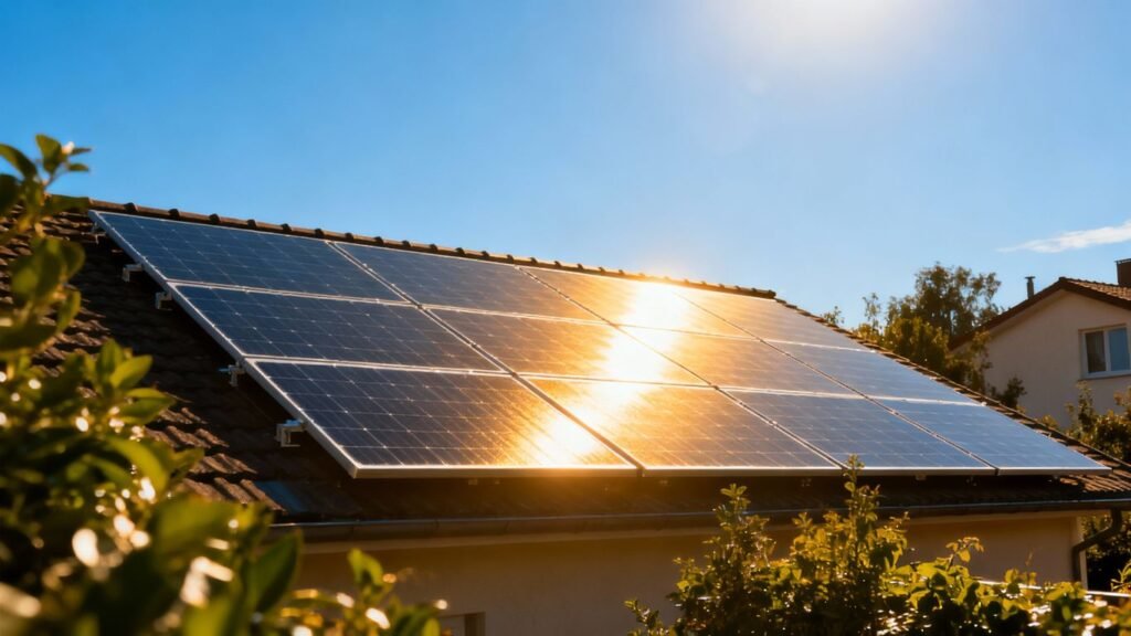
When installing a photovoltaic system, it is often necessary to compile a technical file. This document serves to prove that your installation complies with current standards. To help you understand this more clearly, we will detail the key elements to include in an example photovoltaic installation technical file. It’s a bit like filling out a declaration, but for your solar system. You need to be precise and not forget anything to ensure everything is in order.
Key Points to Remember
- The technical file is mandatory in certain cases to certify the conformity of your photovoltaic installation, particularly for generation installations or high-power consumption installations.
- A clear structure is expected: information about the installation, the installer, and detailed specifications of each component (modules, cables, inverters, batteries).
- It is essential to identify the electrical characteristics of each element, such as the maximum short-circuit current and the open-circuit voltage of the modules, to ensure safety.
- Electrical diagrams, including those for protection and earthing, are essential for visualising and validating the installation’s design.
- Compliance with the NF C 15-100 standard is paramount, and attention must be paid to developments and transition periods of standards for a successful connection.
Understanding the requirements for a photovoltaic technical file
For any photovoltaic installation, compiling a technical file is an essential regulatory step. This document serves as a reference to certify the conformity of your installation with current standards. It is important to understand when this file is required and its precise function in the approval process.
Identifying cases requiring a technical file
A technical file is not systematically requested for every solar installation. It becomes mandatory in several specific situations, particularly for energy generation installations. For example, a technical file is required for a grid-connected photovoltaic installation, whether or not it is equipped with batteries. It is also necessary for consumption installations where the power at the delivery point exceeds 36 kVA, or for bidirectional charging stations for electric vehicles. In some cases, the presence of an inspection report may waive the need for this file, but it is always best to check the precise requirements.
Distinction between consumption and generation installations
It is essential to differentiate installations according to their purpose. Consumption installations are those that produce electricity primarily for self-consumption, without significant injection into the public grid. Generation installations, on the other hand, aim to inject the electricity produced into the grid. The nature of your installation will determine the type of technical file to complete and the associated certificate of conformity. For example, a generation installation without micro-inverters and without batteries will require a specific file, such as SC144A-4, whilst an installation with micro-inverters and batteries will require a different file, such as SC144C2-2.
Role of the technical file in the certificate of conformity
The technical file plays a central role in obtaining the certificate of conformity, a document issued by approved bodies such as Consuel. It proves that the installation complies with safety rules and technical standards, particularly the NF C 15-100 standard. The file details the characteristics of the equipment (modules, cables, inverters), electrical diagrams, and the protection measures implemented. Without a correctly completed and validated technical file, the certificate of conformity cannot be issued, which is essential for connecting your installation to the electricity grid. It is therefore crucial to complete it carefully, referring to the technical data sheets of the components and available completion guides, such as those for calculating peak power.
Rigour in compiling the technical file guarantees the safety of the installation and facilitates its acceptance by grid operators and inspection bodies.
Structure and content of the technical file
The technical file is a key element for any photovoltaic installation. It serves as a reference to ensure that the system complies with current standards and has been installed correctly. Ensuring it is properly completed will lead to a smoother process later on.
Information relating to the installation and site
This section requires detailing the exact address of the installation, as well as the characteristics of the building concerned. It should mention the type of construction, the year of build, and whether any significant renovation work has been carried out recently. It is also important to specify the precise location of the panels on the roof or on the ground, indicating their orientation and inclination. This information helps to assess solar exposure and installation conditions.
Details concerning the installer
Here, you must provide complete information about the company that carried out the installation. This includes the company name, address, telephone numbers, and identification numbers (such as the SIRET number). It is also requested to mention the name of the person responsible for the site and their qualifications. The installer’s qualification is a guarantee of reliability. You must ensure that the installer holds the necessary certifications for this type of work.
Specifications of the installation components
This is the core of the technical file. All elements that make up the photovoltaic installation must be listed. This includes solar panels, the inverter, batteries (if present), cables, and protection devices. For each component, the brand, model, and main technical characteristics must be indicated. For example, for panels, their nominal power, open-circuit voltage, and short-circuit current will be mentioned. For the inverter, its power, efficiency, and maximum input voltage will be specified. The correct selection of components is essential for the system’s performance and safety. You can find information on the necessary components on websites specialising in solar system components.
Here is an example table for solar panels:
| Characteristic | Value |
|---|---|
| Brand | SunPower |
| Model | SPR-X21-415-COM |
| Nominal Power (Wp) | 415 |
| Open Circuit Voltage (Voc) | 47.5 V |
| Short Circuit Current (Isc) | 10.5 A |
It is also important to describe the panel mounting system, specifying the type of structure and the materials used. The technical documentation from the manufacturers of each piece of equipment must be attached to the file. Adherence to installation procedures is paramount.
Identification of photovoltaic modules
To compile a complete and compliant photovoltaic technical file, precise identification of the solar modules is a fundamental step. This involves gathering specific technical information that will guarantee the safety and performance of your installation. It is therefore necessary to fully understand the electrical characteristics of each panel to correctly integrate them into the overall system calculations.
Determining the maximum short-circuit current
The maximum short-circuit current (Isc) of a photovoltaic module is essential data. It represents the maximum current that the module can produce under short-circuit conditions. This value is usually found in the manufacturer’s technical data sheet, often in a section dedicated to electrical characteristics. It is important to note this value for sizing protection devices and cables. You must ensure that you use the maximum Isc value specified by the manufacturer for the module used.
Calculating the maximum open-circuit voltage
The maximum open-circuit voltage (Voc) is the voltage produced by the module when no current is flowing. To obtain the maximum voltage of the photovoltaic generator (Uocmax), you must multiply the Voc of a single module by the total number of modules connected in series in the same string. This value is crucial for sizing DC components, particularly inverters and protection devices, to ensure they can withstand the maximum expected voltage, even in extreme cold conditions where the voltage can increase.
Sources of information for module characteristics
Information relating to the electrical characteristics of photovoltaic modules, such as short-circuit current (Isc) and open-circuit voltage (Voc), is available from several reliable sources. The first and most important is the technical data sheet provided by the module manufacturer. This document details all electrical and mechanical specifications. This information can also be found on the label affixed to the back of each module. For certification and compliance purposes, it is recommended to consult product certificates and third-party test reports, which attest to the modules’ conformity with current standards. Using this data ensures that the components of your solar system are correctly sized.
Here is a summary table of key information to look for:
| Electrical Characteristic | Symbol | Description | Main Source |
|---|---|---|---|
| Maximum Short-Circuit Current | Isc | Maximum current in short-circuit | Manufacturer’s technical data sheet |
| Open Circuit Voltage | Voc | Maximum voltage without load | Manufacturer’s technical data sheet |
| Maximum Power | Pmax | Maximum power under STC conditions | Manufacturer’s technical data sheet |
| Current at Maximum Power | Imp | Current under STC conditions | Manufacturer’s technical data sheet |
| Voltage at Maximum Power | Vmp | Voltage under STC conditions | Manufacturer’s technical data sheet |
Specifications for cables and electrical protection
To ensure the safety and performance of your photovoltaic installation, the choice of cables and electrical protection is a crucial step. It’s not just about choosing components, but about ensuring they meet the standards and specific constraints of your system.
Characteristics of the main photovoltaic cable
The main cable, which connects your solar panels to the inverter, must be carefully selected. It is essential to know its cross-section, which must be adapted to the installation’s power and the distance covered to minimise losses. The maximum voltage the cable can withstand, often indicated by ‘U’ on its technical data sheet, is also a critical parameter. Furthermore, the permissible temperature on the cable core must be considered, especially in hot regions or if the cable is exposed to the sun. For example, a 183kV type PV cable, often black (RAL 9005), uses tinned copper as a conductor and must comply with a specific bending radius according to DIN VDE standards. It is important to consult the technical data sheet for this precise information, such as that relating to insulation resistance.
Parameters of the general DC disconnect switch
The general DC disconnect switch plays a major safety role. It must be capable of withstanding a maximum voltage (‘Un’) and a maximum short-circuit current (‘In’) that correspond to the characteristics of your panel string. These values are also found on the component’s technical data sheet. This device allows the installation to be isolated when needed, an essential operation during maintenance or in an emergency.
Requirements for battery cable protection
If your installation includes a battery storage system, specific protection is required on the battery cable. The maximum voltage (‘Un’) and maximum current (‘In’) that the battery cut-off switch can handle must be specified. It is also important to state whether this switch is integrated into the battery casing or if it is a separate component. For most installations, sections relating to protection against indirect contact and earthing polarity can be marked as not applicable, except in specific cases.
The choice of cables and electrical protection is a step that allows for no approximation. Poor selection can lead to overheating, energy losses, or even fire risks. It is therefore essential to refer to the technical specifications of each component and ensure their compatibility with the entire photovoltaic system. A well-installed cabling system, such as that found in a solar carport system, guarantees the longevity and efficiency of your energy production.
Inverter selection and configuration
Choosing the inverter is a key step for the proper functioning of your photovoltaic installation. This device is responsible for converting the direct current (DC) produced by your solar panels into alternating current (AC), which can be used by your electrical appliances and the grid. It is therefore important to select it carefully. There are different types of inverters, each with its own specific features. The centralised inverter is the most common for residential installations, but for more complex configurations or with partial shading, micro-inverters or optimisers may be a better solution. You must ensure that the chosen inverter is compatible with the total power of your panels and with the other components of your system, such as batteries if you have them. Compatibility with safety standards is also paramount.
Photovoltaic inverter identification
To identify the appropriate inverter, several criteria must be considered. First, you need to check its nominal power, which must be in line with the power of your solar panel array. The maximum DC input voltage of the inverter must also be greater than the maximum open-circuit voltage of your panel string. The brand and model are pieces of information that must be accurately recorded in the technical file. It is also necessary to ensure that the inverter has the required certifications, such as VDE0126, which attests to its conformity with safety standards for grid connection. The choice of a suitable inverter is therefore essential.
Inverter management for installations with batteries
If your installation includes a battery storage system, inverter management takes on an additional dimension. You must then opt for a hybrid inverter or a system combining a solar inverter and a battery charger. This inverter must be capable of managing bidirectional energy flows: charging the battery from the solar panels, powering the house from the panels or the battery, and potentially reinjecting any surplus into the grid. Compatibility between the inverter and your battery technology (lithium, lead, etc.) is a point not to be overlooked. You must also check the inverter’s specifications regarding battery charge and discharge management.
Verification of required inverter certifications
The inverter’s compliance with current standards is a regulatory requirement. The most common certifications for solar inverters in France include the VDE0126 standard, which concerns protection against overvoltages and insulation faults, and the CEI 62109 standard for power converter safety. It is imperative to obtain the VDE0126 certificate for the inverter, usually available on the technical data sheet or in the manufacturer’s documents section. This certificate is an essential document to attach to the technical file for connection. The use of an uncertified inverter may result in the rejection of your connection request. It is also possible to use optimisers, which are compatible with most inverters and panels, and whose compatibility must be checked.
The choice of inverter must be made carefully, taking into account power, voltage, battery compatibility, and certifications. It is a central element of your photovoltaic installation.
Battery storage system management
Integrating battery storage systems into a photovoltaic installation adds a layer of complexity that requires particular attention when compiling the technical file. It’s not just about connecting batteries, but about ensuring that the entire system operates safely and in compliance with current standards. This involves a thorough understanding of the characteristics of each component and their interaction.
Identification of solar batteries and their voltage
The first step is to precisely identify the solar batteries used. Their brand, model, technology (lead-acid, lithium-ion, etc.) and especially their nominal voltage must be noted. This voltage is a key parameter for sizing protection devices and cabling. For example, a 48V battery will not have the same requirements as a series battery system totalling 400V. It is important to consult the manufacturer’s technical documentation to obtain this precise information. Incorrect identification can lead to calculation errors and non-conformities.
Choosing appropriate protection for batteries
Batteries, particularly energy storage systems, require specific protection to prevent overcurrents, short circuits, and overvoltages. This typically includes DC fuses or circuit breakers adapted to the voltage and maximum current the system can deliver. The choice of these protection devices must take into account the breaking capacity required to safely interrupt a potential fault. Protection against overcharging and deep discharge, often managed by the integrated battery management system (BMS) or by external devices, must also be considered. Compliance with the NF C 15-100 standard is paramount here to guarantee the safety of the installation and users. It is often necessary to include diagrams detailing these protection devices in the technical file.
Calculation of short-circuit currents for battery strings
The calculation of the maximum short-circuit current (Icc) is an essential technical step for the correct sizing of protection devices. For a battery string, the Icc depends on the system voltage, the internal resistance of the batteries, and the cable resistance. Battery manufacturers generally provide data on their ability to deliver a high short-circuit current for a short duration. It is imperative to perform this calculation accurately to select fuses or circuit breakers capable of withstanding and interrupting these fault currents. An erroneous calculation could lead to undersized protection, unable to effectively protect the system in case of a problem, which represents a major safety risk. This calculation is often a specific section of the photovoltaic technical file to be completed with care.
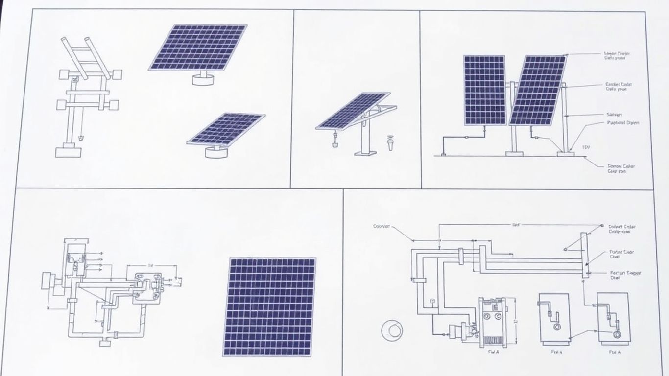
Diagrams and electrical connections
The clarity and precision of electrical diagrams are paramount to demonstrating the conformity of your photovoltaic installation. These visual documents serve as a roadmap for technicians and inspectors, ensuring that all connections are made according to current standards.
Representation of protection against indirect contact
It is essential to clearly represent the protection devices implemented to prevent risks related to indirect contact. This includes earthing metallic structures and equipment, as well as the choice of appropriate residual current devices. A good illustration of these protection measures facilitates understanding of the safety measures adopted for your installation.
Earthing diagram for autonomous installations
For autonomous photovoltaic systems, the earthing diagram is particularly important. It must detail how the mass of each piece of equipment is connected to the main earthing system. This diagram ensures that any insulation fault will be correctly discharged, thereby protecting users and equipment. It is important to distinguish this diagram from that of a grid-connected installation, as requirements may vary.
Integration of diagrams into the technical file
All diagrams, whether for protection against indirect contact or earthing connections, must be integrated logically and legibly into your technical file. Each diagram must be clearly labelled and accompanied by explanatory legends. Ensure that these representations accurately correspond to the actual configuration of your installation. Good organisation of the diagrams greatly contributes to the rapid validation of your file by inspection bodies, such as Consuel. For more details on solar system design, you can consult the steps for designing an installation.
Here is a simplified example of what an earthing diagram for an autonomous installation might contain:
| Component | Earthing Connection Point | Conductor Type |
|---|---|---|
| Mounting structure | Main earthing terminal | Multi-strand copper wire |
| Inverter casing | Main earthing terminal | Multi-strand copper wire |
| DC protection box | Main earthing terminal | Multi-strand copper wire |
| Batteries (if metallic) | Main earthing terminal | Multi-strand copper wire |
Specific cases and associated forms
Each photovoltaic installation, depending on its configuration and specific characteristics, may require specific forms to certify its conformity. It is therefore essential to correctly identify the type of installation and the connection method to select the right documents. For example, an installation with micro-inverters and a battery will not follow the same administrative path as an installation without these elements.
There are several scenarios that require particular attention when compiling the technical file. These situations are often related to specific connection configurations or the integration of storage systems. Here is a breakdown of the most common cases:
- Installations with micro-inverters and battery: These systems, often more complex, require dedicated forms that take into account the specific features of micro-inverters and the management of stored energy in the battery. The certificate of conformity will generally be purple, accompanied by a specific technical file such as SC 144C2-2, potentially supplemented by an SC 144E depending on the connection case.
- Installations without micro-inverters or battery: For more conventional installations, without storage or micro-inverters, the forms may be simpler. The certificate will be blue, and the associated technical file will depend on the type of connection, for example an SC 144A-5 for a CAS 3 type connection.
- Other generation configurations: Installations that are not strictly photovoltaic, or that have particular generation characteristics, will require forms such as SC 144D-5, again, often supplemented by an SC 144E for more complex connection cases (CAS 4).
It is important to note that a transition period is underway for the application of new standards. Until 31 May 2026, it is possible to use older versions of technical files, provided they are accompanied by the SC 144E file for cases 3 and 4. After this date, only new versions will be accepted. It is therefore advisable to adapt quickly to the new requirements to avoid any administrative blockage. A good understanding of these distinctions is essential for a successful submission of your file, as shown by the examples of forms.
Selecting the correct form is a key step. It ensures that all aspects of your installation are properly documented and comply with current regulations. An error in choosing the form can lead to significant delays in the validation and connection process.
Submission and validation process
Once your technical file has been meticulously prepared, the next step is to submit it for validation. This process is essential to confirm the conformity of your photovoltaic installation with current standards and to obtain the necessary authorisations for connection.
Creation and completion of the certificate of conformity
The first action is to obtain and complete the certificate of conformity. This official document, often issued by an approved inspection body such as Consuel, summarises the characteristics of your installation. It is imperative to complete it with the utmost precision, including all information relating to your project, the components used, and the installer. An error or omission at this stage can lead to significant delays in the validation process. It is often necessary to create a customer account on the organisation’s platform to manage your procedures. Purchasing the certificate corresponding to your type of installation is a key step.
Downloading associated documents
Your complete technical file, including all electrical diagrams, technical data sheets for components (modules, inverters, batteries, cables) and required certifications, must be attached to your application. These documents serve as tangible proof of your installation’s conformity. It is recommended to organise them clearly and logically before uploading them via the dedicated platform. Ensure that all files are in accepted and readable formats. Sometimes, an external inspection report may replace the need to attach a specific technical file, depending on the case.
Preparation for the appointment with the inspector
In some cases, a visit to the installation by an inspector may be required. It is therefore wise to prepare for this event. This involves ensuring that the physical installation corresponds exactly to what is described in the technical file and the certificate. Having the original documents, equipment invoices, and proof of the installer’s qualifications readily available can greatly facilitate this step. Good organisation and a clear understanding of your own installation are your best assets for a smooth validation. Compliance with standards, such as NF C 15-100, is at the heart of this inspection.
Regulatory compliance and applicable standards
For your photovoltaic installation to be recognised and connected to the grid, it is imperative to comply with a set of rules and standards. This guarantees that your system is safe and functions correctly. Regulatory compliance is not just an administrative formality; it ensures the safety of people and property, as well as the longevity of your installation.
Application of the NF C 15-100 standard
The NF C 15-100 standard is the main reference for all electrical installations in France, including those incorporating solar panels. It details the requirements for the design, implementation, and verification of electrical installations. For photovoltaic systems, this includes specific requirements concerning DC cabling, protection against overcurrents and overvoltages, and earthing. It is important to fully understand the different sections of this standard to avoid any errors during installation. For example, protection against indirect contact must be rigorously applied, which may involve specific measures depending on your system’s configuration, particularly for autonomous installations where the earthing diagram takes on particular importance.
Management of transition periods and standard versions
The world of solar energy is evolving rapidly, and with it, the standards that govern it. The NF C 15-100 standard, for example, has undergone updates, notably with a new edition planned for August 2024. These changes may affect the documents to be provided for the conformity application. There are transition periods where old and new versions of technical files can coexist, but with specific conditions. For example, between 1 September 2025 and 31 May 2026, it will be possible to use older versions of technical files, provided they are supplemented with a specific technical file (such as SC 144E) for certain connection cases (cases 3 and 4). From 1 June 2026, only new versions will be accepted. It is therefore advisable to keep informed of these developments to anticipate changes and facilitate your procedures.
Importance of compliance for grid connection
Obtaining a certificate of conformity, often issued by an organisation such as CONSUEL, is a mandatory step to connect your photovoltaic installation to the electricity grid. This certificate attests that your installation complies with current standards and is secure. Without this document, the grid operator will not be able to authorise the connection, and you will not be able to benefit from selling surplus electricity or injecting it into the grid. For generation installations, a specific technical file (for example, SC 144) must accompany the certificate of conformity. Similarly, for consumption installations, various technical files (SC 143, SC 145, etc.) are required depending on the power and configuration, particularly in the presence of bidirectional charging stations. Complying with regulatory requirements ensures a smooth integration of your solar system, whether for self-consumption or total resale of your production.
Here is an overview of the technical files to be attached according to the type of installation and connection:
| Type of installation | Type of connection | Technical file to attach (Blue/purple certificate) |
|---|---|---|
| Photovoltaic without micro-inverter, without battery | CAS 1 | SC 144A-4 |
| Photovoltaic without micro-inverter, without battery | CAS 3 | SC 144C-4 |
| Photovoltaic with micro-inverter, with battery | CAS 2 | SC 144C2-2 + SC 144E |
| Non-photovoltaic generation installation | CAS 4 | SC 144D-5 + SC 144E |
It should also be noted that for certain installations, such as a solar carport, obtaining a certificate of conformity is necessary for grid connection, which involves submitting technical documents and an inspection visit to obtain the certificate.
Regarding regulatory compliance and the rules to follow, we ensure that everything is in order. It is important to comply with current standards to guarantee the safety and efficiency of your solar installation. To find out more about the regulations that apply to your project, visit our website today!
Conclusion: The importance of the technical file for your photovoltaic installation
So, we have together covered the key steps to compile a solid technical file for your photovoltaic installation project. It’s true, it might seem a bit overwhelming at first, with all this information to gather and these forms to fill in. But see it as an investment: a well-prepared file is a guarantee that your installation will be compliant, secure, and will function as expected. It avoids problems later on, whether with inspection bodies or even for selling your surplus electricity. Remember that every detail counts, from the voltage of your panels to the cross-section of your cables. If in doubt, do not hesitate to refer to guides or ask for advice. A well-documented installation is an installation that will bring you long-term satisfaction.
Frequently Asked Questions
What is a technical file for a photovoltaic installation?
It is a set of documents that proves your solar installation complies with all safety rules and current standards. It’s a bit like the detailed instruction manual for your solar system.
When do I need to create a technical file?
Generally, a technical file is required if your solar installation is intended to generate electricity for sale or if it is quite large (over 36 kVA for consumption). Sometimes, it is also requested for installations with special charging stations for electric cars.
What is the difference between an installation for consumption and one for generation?
A consumption installation is when you produce electricity for your own home. A generation installation is when you produce more electricity than you consume, often to sell it. The rules and required documents may differ.
Where can I find information about the solar panels for my file?
Important details such as the short-circuit current (when it’s not working) or the open-circuit voltage (when nothing is connected) can be found on the technical data sheet for each panel. You can also multiply these values by the number of panels to get the figures for the entire string.
What information do I need to provide about cables and protection devices?
You need to specify the size of the cables (their cross-section), the maximum voltage they can withstand, and the temperature they can tolerate. For switches, you need to indicate their voltage and the maximum current they can handle in case of a problem.
How do I choose the right inverter and what certifications are necessary?
The inverter converts the current produced by the panels into usable household current. You need to choose a model suitable for your installation and verify that it has the mandatory certifications, such as the VDE standard, which guarantees its safety and performance.
What should I know about batteries in a technical file?
If you have batteries, you need to indicate their voltage and choose the correct protection devices to prevent overcurrents. You also need to calculate the maximum short-circuit current for battery strings, similar to solar panels.
Why are electrical diagrams so important in the file?
The diagrams show how everything is connected: the panels, cables, protection devices, inverter, and how everything is earthed. They allow verification that the installation is done correctly and safely, especially to prevent electric shocks.