Choosing the right cable for a photovoltaic installation is a bit like choosing the right shoes for a long hike: it can really make all the difference. You don’t just use any old thing, especially when you consider the lifespan and safety of the installation. Solar cables aren’t just electrical wire; they have to withstand the sun, cold, humidity, and, most importantly, handle voltages that can be quite high. In this article, we’re going to look at what you need to know about photovoltaic cable standards and why they’re not the same as a cable you’d use to plug in your lamp.
Key Points to Remember
- The EN 50618 standard is the benchmark for modern photovoltaic cables, especially those designed for 1500V DC voltages, an evolution that improves the profitability of installations.
- Solar cables differ from standard cables in their ability to withstand higher voltages between conductor and earth (1500V vs 900V), as well as their increased resistance to harsh outdoor conditions and extended lifespan.
- Several types of common photovoltaic cables exist, such as the TOPSOLAR® range, which vary by their conductor (tinned copper or aluminium) and their sheath (XLPE, LSZH, PVC), offering specific resistances to UV, ozone, and water (AD8).
- The choice of optimal cable depends on the installation’s current and voltage, environmental conditions, as well as the cross-section and length required to minimise energy losses.
- In addition to the EN 50618 standard, other regulations such as IEC 62930, NF C 15-100, and the European CPR regulation on fire reaction are important to ensure the safety and compliance of solar installations.
Understanding the EN 50618 photovoltaic cable standard
The EN 50618 standard represents a significant evolution in the field of cables for photovoltaic installations. It was specifically developed to meet the increased requirements of modern solar systems, particularly their transition to higher operating voltages. Before this standard, standard cables were no longer sufficient to guarantee long-term safety and performance.
Evolution towards a 1500V DC voltage
The photovoltaic industry has undergone a major transformation with the increase in the operating voltage of solar panels, moving from 1000V to 1500V DC. This evolution, driven by the pursuit of better project profitability, helps reduce overall costs, extend connection range, and minimise the number of junction boxes required. This increase in voltage naturally necessitated an adaptation of all DC circuit components, including cables. The EN 50618 standard was created to frame this new situation, specifying requirements adapted to these higher voltages. It is important to note that this standard has become an international reference, often required by the IEC 61730 standard for the safety qualification of PV modules.
Requirements of the EN 50618 standard for PV cables
The EN 50618 standard imposes precise technical characteristics for photovoltaic cables. It notably defines a nominal continuous voltage of up to 1500V DC. Compliant cables must offer reinforced insulation and an outer sheath, capable of resisting external aggressions such as ultraviolet (UV) rays, ozone, and extreme temperature variations. Furthermore, high flexibility and an extended lifespan are expected, often guaranteed for 25 years under normal operating conditions. These requirements aim to prevent premature degradation, such as cracks or corrosion, which can lead to electrical losses and high maintenance costs. It is therefore essential that professionals verify the compliance of cables offered by their suppliers with this specific standard, as it establishes stricter requirements than those for general low-voltage electrical cables.
IEC 61730 compliance and the EN 50618 standard
The EN 50618 standard is closely linked to the international IEC 61730 standard, which concerns the safety qualification of photovoltaic modules. For a PV module to be certified according to IEC 61730, the cables used in its design must imperatively comply with the EN 50618 standard. This interdependence highlights the crucial importance of the EN 50618 standard in the ecosystem of solar installation safety and performance. It guarantees that the cables are not only suitable for high voltages but also possess the necessary robustness to ensure the longevity and reliability of the installation in often difficult environmental conditions. Adherence to these standards is a key step to ensure the safety of your installation.
Fundamental differences between photovoltaic and standard cables
It’s easy to think a cable is just a cable, but in the world of photovoltaics, things are a bit more complex. Standard cables you might find for a domestic electrical installation are simply not suitable for connecting your solar panels. Why? Because the operating conditions and requirements are very different. PV cables are designed to withstand much harsher stresses and for a much longer lifespan. Ignoring these differences can lead to safety problems and reduced performance of your installation.
Permissible voltage and voltage between conductor and earth
The most striking difference concerns voltage. Modern solar installations often operate at higher DC voltages, typically 1500V DC, to optimise efficiency and reduce the number of connections. Standard cables, on the other hand, are generally designed for lower voltages, often around 1000V DC for the maximum voltage between conductor and earth. Photovoltaic cables, compliant with standards like EN 50618, must reliably withstand this increased voltage over the long term. This means more robust insulation and materials capable of maintaining their electrical integrity even under high stress.
| Cable type | Voltage between conductor and earth (Uo) | Voltage between conductors (U) |
|---|---|---|
| Standard cable (e.g., RV-K 0.6/1kV) | 0.9 kV | 1.5 kV |
| Solar cable (e.g., H1Z2Z2-K 1.5/1.5kV) | 1.5 kV | 1.5 kV |
Resistance to extreme environmental conditions
Your solar panels are outdoors, exposed to everything nature can throw at them: intense sun, rain, wind, temperature variations, ozone, and sometimes even animals. A standard cable is not made for this. Photovoltaic cables are specifically designed to resist these aggressions. They often feature an outer sheath resistant to UV, ozone, and humidity (AD8 classification, for example), which ensures they will not degrade prematurely due to the elements. This resistance is key to the longevity of the installation.
Lifespan and ageing tests
A photovoltaic installation is a long-term investment, often designed to last 25 years or more. Cables must therefore keep up. PV cables undergo accelerated ageing tests that simulate decades of exposure to operating conditions. These tests, such as the Arrhenius test, allow the extrapolation of the cable’s real lifespan. An endurance requirement of 120°C for 20,000 hours, or 25 years at 90°C, is often mentioned. A standard cable does not offer this level of guarantee and might require replacement long before the expected end of life of your panels, leading to additional costs and production interruptions.
Identification of common photovoltaic cables
In the field of solar installations, several types of cables are specifically designed to meet the unique requirements of direct current (DC) and sometimes harsh environmental conditions. It is important to distinguish them from standard electrical cables to ensure the safety and performance of your system. Among the most common references, several TOPSOLAR® product ranges can be found.
The TOPSOLAR® H1Z2Z2-K cable
This cable is a benchmark in the photovoltaic world, specially designed for installations operating under a continuous voltage of 1500V. Its design is based on a tinned copper conductor, a choice dictated by the standard to prevent corrosion. The insulation and outer sheath are made of LSZH (Low Smoke Zero Halogen) material, which means that in the event of a fire, it emits little smoke and no halogens, a major asset for safety. It is TÜV EN50618 certified, attesting to its compliance with the 1500V DC voltage requirements, a minimum lifespan of 20,000 hours at 120°C (and over 25 years at 90°C), and immersion resistance (AD8), superior to the AD7 standard. Furthermore, it is UV resistant and complies with the European CPR regulation with a Dca-s2a,d2,a2 classification.
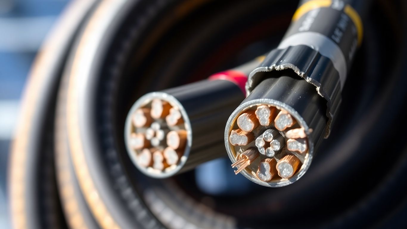
The TOPSOLAR® PV AL cable
This range uses class 2 aluminium conductors, an alternative often employed for larger cross-sections. Insulation is provided by XLPE (Cross-linked Polyethylene), and the outer sheath is PVC. This cable also benefits from AD8 classification for its immersion resistance and is designed to be UV resistant. Commonly found cross-sections range from 1×95 mm² to 1×300 mm², typically used to connect inverters to transformers or for larger scale connections. Although a specific standard for 1500V aluminium cables is still under development, this type of cable is widely used.
The TOPSOLAR® PV AL 1500 HEAVY DUTY cable
This is a reinforced version of the PV AL cable. It retains the class 2 aluminium conductor and XLPE insulation but is distinguished by a halogen-free outer sheath (LSZH). This characteristic makes it safer in the event of a fire. Like its predecessor, it is UV resistant, which is essential for outdoor applications where sun exposure is constant. This cable is also designed for 1500V voltages and is suitable for demanding environments.
It is imperative to verify the compliance of cables with current standards, particularly the EN 50618 standard for photovoltaic installations. These standards define stricter requirements than those for general electrical cables, especially regarding the permissible voltage between conductor and earth, which is 1500V for PV cables compared to 900V for standard cables. Precise technical documentation, such as an installation technical file, is essential to attest to the compliance of all system components.
Technical characteristics of photovoltaic cables
Photovoltaic cables are designed to withstand extreme conditions and ensure a long lifespan. Their technical specifications guarantee the safety and performance of your solar installation over the long term.
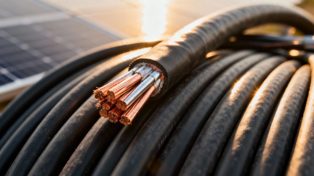
Tinned copper and aluminium conductors
The choice of conductor material is paramount. For photovoltaic cables, there are mainly two options: tinned copper and aluminium. Tinned copper is often preferred for its corrosion resistance, a major asset in outdoor environments subject to humidity. It is generally used in smaller cross-section cables, such as the TOPSOLAR® H1Z2Z2-K. Aluminium, on the other hand, is a lighter and more economical alternative, particularly suitable for the large cross-sections required for power connections, as in the case of TOPSOLAR® PV AL cables. The EN 50618 standard requires a tinned copper conductor for cables certified under this standard, to prevent corrosion.
Insulation and outer sheath (XLPE, LSZH, PVC)
The protection of conductors is ensured by specific insulation and sheathing materials. Cross-linked polyethylene (XLPE) is a commonly used insulator for its robustness and thermal resistance. The outer sheath can be made of polyvinyl chloride (PVC), offering good mechanical protection, or of halogen-free and low smoke emission materials (LSZH – Low Smoke Zero Halogen). LSZH cables are recommended for their improved behaviour in case of fire, limiting flame propagation and the toxicity of fumes, which is a significant advantage for installation safety. The European CPR standard classifies these cables according to their reaction to fire; for example, a cable can be classified Dca-s2a,d2,a2.
Resistance to UV, ozone and weathering (AD8)
Photovoltaic cables are constantly exposed to external aggressions. They must therefore exhibit excellent resistance to the sun’s ultraviolet (UV) rays, which can degrade insulating materials over time. Resistance to ozone, another component of the atmosphere, is also essential to prevent sheath cracking. Furthermore, the standard often specifies a weather protection rating, such as the AD8 rating, which attests to the cable’s ability to resist prolonged immersion in water. This combination of resistances guarantees the longevity and reliability of the cabling, even in the harshest climatic conditions. A well-designed installation must take these factors into account to ensure the performance of the entire system.
Selection criteria for an optimal photovoltaic cable
Choosing the right cable for your solar installation is a bit like choosing the right shoes for a long hike: it can make all the difference between a pleasant experience and a real ordeal. We cannot afford to overlook this step, as an unsuitable cable can cause performance issues, or even long-term safety problems. It really needs serious consideration.
Adaptation to the installation’s current and voltage
The first thing to look at is the power of your installation. Cables must be able to withstand the current (amperage) and voltage (in Volts) without overheating or premature wear. Modern installations often operate at higher voltages, up to 1500V DC, which requires specific cables. You need to ensure that the cable’s cross-section is sufficient for the current it will carry. A cross-section that is too small will cause it to heat up, which increases energy losses and can even become dangerous. Think of it like a water pipe: if the pipe is too thin for the flow, the pressure drops and the water doesn’t go as far. For grid-connected installations, the cable must also comply with the grid’s requirements, as stipulated by standard [b3d8].
Consideration of specific environmental conditions
Photovoltaic cables are outdoors, exposed to everything: sun, rain, wind, temperature variations, sometimes even ozone. They must therefore be robust. We’re talking about resistance to UV, humidity (often classified AD8, meaning they can be submerged), and temperature variations. If your installation is by the sea, you’ll need to consider salt resistance. If it’s in a very sunny region, UV protection is paramount. Ignoring these aspects risks rapid cable degradation, loss of efficiency, and costly replacements. The lifespan of a solar installation is measured in decades; the cables must keep up.
Importance of cable cross-section and length
The cable’s cross-section is its internal diameter, and it is directly related to the amount of current it can carry without problems. The stronger the current, the larger the cross-section must be. But be careful, the cable’s length also plays a role. The longer a cable is, the more electrical resistance increases, leading to a voltage drop. This voltage drop, even if small, can reduce the overall performance of your installation. Therefore, you need to find the right balance: a cross-section large enough for the current, but not excessively large to avoid increasing cost and weight, while also considering the distance to be covered. It is often necessary to consult tables or calculators to determine the optimal cross-section based on current, length, and acceptable voltage drop. Adhering to current electrical standards, such as [5fcf], is a key step to ensure safety and performance.
Other standards and regulations applicable to solar cables
Beyond the EN 50618 standard, several other international or national regulations and standards govern the choice and use of cables in photovoltaic installations. It is important to be aware of them to ensure the safety, performance, and compliance of your system.
The international standard IEC 62930
The IEC 62930 standard is an international reference that specifies requirements for cables intended for photovoltaic systems. It complements the EN 50618 standard by addressing aspects such as resistance to environmental conditions specific to solar installations, durability, and electrical safety. It aims to ensure that cables can withstand the stresses associated with prolonged exposure to sun, temperature variations, and humidity. This standard is particularly relevant for new generation cables, designed for increased performance and extended lifespan.
The French standards NF C 15-100
In France, the NF C 15-100 standard governs low-voltage electrical installations, including those of photovoltaic systems. Although it is not specific to solar cables like EN 50618, it imposes general rules concerning wiring, circuit protection, earthing, and current separation. It is therefore necessary to ensure that photovoltaic cabling also complies with these general requirements for a compliant installation. For example, the physical separation of DC and AC circuits is a key requirement of this standard.
The European CPR regulation on fire reaction
The European CPR (Construction Products Regulation) concerns the classification of construction products according to their reaction to fire. For cables used in photovoltaic installations, CPR is mandatory and ensures that cables present a controlled level of fire safety. Different fire reaction classes exist (A, B, C, D, E, F), and the choice of the appropriate class will depend on the specific application and local regulations. Adequate classification is essential to limit fire spread and ensure the safety of people and property. Installers must check the CPR labelling on cables to ensure their compliance. Solar cables must often meet specific requirements for fire resistance, in addition to their resistance to weathering and UV.
Role of cables in the design of a photovoltaic installation
Cables are a bit like the nervous system of a solar installation. They transport the electricity produced by the panels to the other components of the system. Choosing the right cables ensures that everything works well and safely in the long term. Cabling can be separated into two main categories: direct current (DC) and alternating current (AC).
DC cabling: from panels to the string box
This is the first stage of electricity’s journey. DC cables connect the solar panels to each other, then route them to the string box (or junction box). This is where several
Safety and performance: the importance of connectors
Connectors are a bit like the Achilles’ heel of photovoltaic installations. You can have the best panels and the most efficient cables, but if the connections aren’t top-notch, everything can be compromised. This is truly where safety and performance are played out daily.
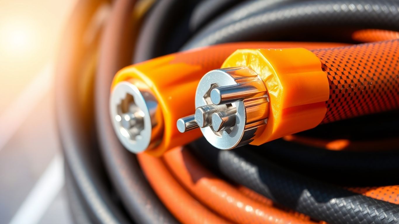
MC4 connectors: industry standard
When we talk about connectors for direct current (DC) in solar, the name that comes up most often is MC4. It has become a bit of a standard, much like USB for our electronic devices. They are designed to be robust, easy to use, and most importantly, to ensure a reliable electrical connection even in difficult conditions. They are generally manufactured to resist UV, humidity, and temperature variations, which is perfect for outdoor use. Their design allows for quick and secure connection, reducing the risk of errors during installation. They are found on almost all solar panel cables today.
Compatibility and risks of mixing brands
So, this is where it can get complicated. Even if many connectors bear the MC4 designation, they are not all interchangeable. Manufacturers have their own tolerances and specifications. Using connectors from different brands on the same connection is a bit like playing Russian roulette. It might seem to work at first, but in the long term, it can cause problems: overheating, poor conductivity, or even disconnections. It is strongly recommended to stick to the same brand for all connectors in a single string of panels. If in doubt, it is better to check certified compatibility or, more simply, use connectors from the same manufacturer as your panels or cables. Compatibility is truly the keyword here.
Ensuring a watertight and secure connection
A watertight connection is vital. Water and electricity don’t mix well, especially with the voltages present in a solar installation. MC4 connectors are designed to be watertight once correctly assembled, often with an O-ring system. But be careful, watertightness also depends on the quality of the assembly. You must ensure that the cable is properly crimped into the connector and that the connector is securely clipped. Specific tools are often recommended for crimping to ensure a solid mechanical connection and good electrical conductivity. A well-made connection is a guarantee of long-term performance and safety, preventing energy losses and fire risks. You also need to consider protecting these connections from mechanical stresses, such as excessive twisting or pulling, which could compromise their integrity. Solar junction boxes play an important role in this protection, housing and securing these critical connection points [f697].
Protection against overcurrents in PV installations
In a photovoltaic installation, protection against overcurrents is a key step to ensure the safety and longevity of your system. This concerns both the direct current (DC) circuit coming from the panels and the alternating current (AC) circuit going to your domestic grid or the public grid.
Circuit breakers and fuses are the guardians of your installation. They are designed to interrupt the current flow when it exceeds a predefined safety threshold. On the DC side, specific fuses for photovoltaics (gPV) or DC circuit breakers are often used. They are particularly necessary if you have several strings of panels connected in parallel, or if there is a risk of reverse current. The general rule for sizing fuses is to ensure that their rating (Ifus) is between 1.5 times the nominal current (In) and 2.4 times this same current, i.e., the formula: 1.5 × In ≤ Ifus ≤ 2.4. On the AC side, a circuit breaker dedicated to the PV installation is mandatory. Its rating must be greater than 1.1 times the nominal current of the inverter, but less than the maximum capacity supported by the cable. An appropriate tripping curve, often type B or C, must also be chosen.
The choice of your cable’s cross-section is not random. It is directly linked to the installed protections. An undersized cable could overheat and become a fire hazard, while an oversized cable represents unnecessary cost. The fundamental rule for safety is the formula Iz >= In. Here, Iz represents the maximum permissible current for the cable, and In is the nominal current of the protected circuit. It is important to consider all factors that can reduce a cable’s capacity, such as ambient temperature, how cables are grouped or laid. For example, for an installation with a desired maximum permissible current of 336.14 A, the cable’s nominal maximum permissible current must be greater than 602.4 A. This may require the use of larger cross-section cables, or even parallel cables, such as two 300 mm² aluminium cables in some cases, to limit voltage drop and losses. A DC voltage drop of less than 2% is often a requirement, which may necessitate larger cable cross-sections over long distances.
Formula Iz >= In for safety
The formula Iz >= In is the cornerstone of cable sizing in photovoltaic installations. It states that the maximum current the cable can safely carry (Iz) must always be greater than or equal to the nominal current of the circuit it supplies (In). Failure to comply with this simple rule can have serious consequences, ranging from cable overheating to a fire hazard, as well as premature degradation of installation components. It is therefore imperative to correctly calculate Iz taking into account installation conditions and correction factors, and to ensure that it is sufficient compared to In defined by the protections (fuses, circuit breakers) and the characteristics of the source (inverter, panels).
Here are some points to consider for sizing:
- Nominal current (In): This is determined by the rating of the circuit breaker or fuse, or by the maximum output current of the inverter.
- Cable permissible current (Iz): This current depends on the conductor’s cross-section, material (copper or aluminium), insulator type, and installation conditions (temperature, grouping, etc.). Manufacturers provide tables of values, and standards such as IEC 60364-5-52 provide precise guidelines.
- Correction factors: These are applied to
Izto account for actual operating conditions. For example, if several cables are grouped, their current carrying capacity decreases. Similarly, a high ambient temperature reducesIz. - Voltage drop: Beyond overcurrent protection, the cable’s cross-section must also be sufficient to limit voltage drop over the cable’s length, so as not to impact the installation’s performance. A DC voltage drop of 2% is a common limit.
Earthing and equipotential bonding of solar installations
To guarantee the safety of your photovoltaic installation and of people, earthing all metallic parts is a non-negotiable step. This concerns the panel frames, mounting structures, and metallic enclosures of equipment such as inverters. The objective is to create a safe path for current in the event of a fault, thus preventing risks of electric shock or fire. Equipotential bonding, on the other hand, aims to equalise electrical potentials between different conductive parts, which is sometimes specifically required by certain inverter manufacturers for their proper functioning.
Earthing of metallic parts
All metallic components of your solar installation must be connected to the earthing system. This includes not only the panels themselves, but also the rails that support them and the inverter enclosures. This connection is generally made using a dedicated protective conductor. It is important to ensure that these connections are solid and durable so that they can effectively play their role when needed. A well-earthed installation is a safety foundation for the entire system.
Minimum cross-section of the protective conductor (PE)
The size of the protective conductor (PE) is not left to chance and must comply with precise rules to be effective. It depends directly on the cross-section of the active conductors of the installation. Here is an overview of common requirements:
| Cross-section of active conductors (mm²) | Minimum PE cross-section (mm²) |
|---|---|
| S ≤ 16 | 16 |
| 16 < S ≤ 35 | S/2 |
| S > 35 | 16 |
These values are there to ensure that the protective conductor can withstand a fault current without excessive overheating. It is always preferable to consult the NF C 15-100 standard or the UTE C 15-712-1 guide for the exact details applicable to your specific situation.
Functional equipotential bonding according to inverters
Beyond safety earthing, some inverter manufacturers specify ‘functional’ equipotential bonding. This is not the same as conventional earthing. It is sometimes necessary for the proper internal functioning of the inverter, for example, to stabilise internal potentials. It is therefore essential to consult the technical documentation of your inverter to find out if this requirement applies to your installation. Ignoring this specification could lead to malfunctions or reduced performance of your system. A good understanding of the manufacturer’s requirements is therefore paramount for a reliable solar installation. You can find information on non-penetrating membrane installation systems here.
Earthing and equipotential bonding are two distinct but complementary concepts for the safety and performance of a photovoltaic installation. The first protects against major insulation faults, while the second may be required for the proper functioning of certain equipment. It is essential to clearly distinguish between the two and to follow normative prescriptions and those of manufacturers.
Ensuring the earthing and equipotential bonding of your solar panels is super important for the safety of your installation. It’s like creating a safe path for electricity in case of a problem, thus protecting your equipment and people. Want to know more about how to make your solar system even safer? Visit our website to discover our solutions and expert advice!
Conclusion: The crucial importance of the photovoltaic cable
In conclusion, the choice of photovoltaic cable is no small matter. It is an element that, although sometimes overlooked, plays a major role in the performance and safety of your solar installation. Adhering to standards, such as EN 50618, and thoroughly understanding the technical specificities of each cable, whether copper or aluminium, is truly necessary. A good selection helps avoid future problems, guarantees stable energy production, and extends the lifespan of your system. Give it careful thought for your next project!
Frequently Asked Questions
Why can’t a normal electrical cable be used for a solar installation?
Normal cables are not designed to withstand the harsh conditions of a solar installation. They must resist high direct current, sunlight (UV rays), temperature variations, and humidity for many years. Solar cables, on the other hand, are specially manufactured for this, with more robust insulation and better resistance to external aggressions.
What is the main standard for solar panel cables?
The main standard to be aware of is EN 50618. It guarantees that the cable can withstand high voltage (up to 1500V DC) and that it is designed to last a long time, resisting UV and weathering. This is a guarantee of safety and performance for your installation.
What is the 1500V DC voltage mentioned for solar cables?
This means that the cable can withstand a voltage of 1500 Volts direct current. Modern solar installations often use this higher voltage to be more efficient and reduce costs. Cables must therefore be able to handle this power without risk.
What are the differences between a solar cable and a standard cable in terms of resistance?
A solar cable is much more resistant. It is made to withstand the sun’s UV rays without degrading, it resists ozone and extreme temperature changes, whether it’s very hot or very cold. Its lifespan is also much longer, as it is tested to operate for 25 years or more.
Why are cable cross-section and length important?
The cable’s cross-section (its thickness) determines the amount of current it can carry without heating up. A cross-section that is too small can cause energy losses and even a fire hazard. The cable’s length affects voltage drop: the longer the cable, the more the voltage can decrease between the panel and the inverter. Therefore, you must choose the correct cross-section and length for the installation to function properly.
Can connectors from different brands be mixed?
It is strongly advised against mixing connectors from different brands, even if they appear identical (like MC4s). They are not always 100% compatible. A poor contact can create overheating, energy losses, or even dangerous electrical arcs for your installation and for you.
What is the role of earthing in a solar installation?
Earthing serves to protect the installation and people against overvoltages or electrical faults. All metallic parts of the installation (panel frames, structures, enclosures) must be earthed. This prevents dangerous current from flowing in case of a problem.
What is an LSZH or halogen-free cable?
LSZH stands for ‘Low Smoke Zero Halogen’, meaning low smoke emission and halogen-free. In the event of a fire, these cables release less toxic and corrosive smoke than conventional PVC cables. This is an important safety measure, especially in public places or homes.